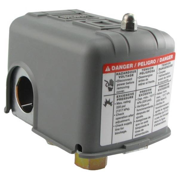
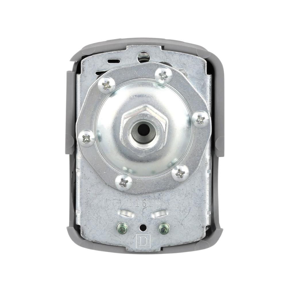
Square D by Schneider Electric 9013FSG52J33 Air-Pump Pressure Switch, NEMA 1, 50-70 psi Pressure Setting, 25-80 psi Cut-Out, 20-30 psi Adjustable Differential 4.8 out of 5 stars 26 $39.09 $ 39. Square D Pumptrol Pressure Switch is compatible with jet pumps, submersible pumps and reciprocating pumps. Offers durability. 7 Commercial Pressure Switches Electromechanical Square D Brand 9013 For power circuits, FSG, FTG, FYG, FRG, FHG, and G When setting the pressure switch, adjust the. How to change a water pump pressure switch.
square d pumptrol pressure switch wiring diagram – Just What’s Wiring Diagram?
Pumptrol 9013FSG standard water pump pressure switches are suitable for all types of pumps, including jets, submersible, and reciprocating. 9013FSG water pump pressure switches are used to control electrically driven water pumps. They are diaphragm actuated. Square D Pumptrol pressure switches are commonly found in many commercial and residential plumbing applications that require the regulation of water pressure. Although Pumptrol pressure switches are generally reliable, sometimes problems can develop with the switch or with the associated water system. Tutorial for understanding and adjusting the cut-in and cut-out pressure settings of Square D™ 9013 Pumptrol Power Pressure Switches. To learn more, please v.
A wiring diagram is a kind of schematic which makes use of abstract photographic symbols to show all the interconnections of parts in a system. Wiring representations are comprised of two things: icons that represent the parts in the circuit, and lines that stand for the links in between them. For that reason, from circuitry diagrams, you understand the relative location of the parts and also how they are linked. It’s a language engineers should discover when they function on electronic devices tasks.
square d pumptrol pressure switch wiring diagram
 Wiring Diagram Sheets Detail:
- Name: square d pumptrol pressure switch wiring diagram – famous best square d pressure switch wiring diagram festooning rh winkeel info Air pressor Pressure Switch Diagram Air pressor Pressure Switch Diagram
- File Type: JPG
- Source: bookmyad.co
- Size: 309.63 KB
- Dimension: 1814 x 970
Wiring Diagram Sheets Detail:
- Name: square d pumptrol pressure switch wiring diagram – 56 New Pressure Switch Circuit Diagram
- File Type: JPG
- Source: golfinamigos.com
- Size: 81.30 KB
- Dimension: 675 x 372
Wiring Diagram Sheets Detail:
- Name: square d pumptrol pressure switch wiring diagram – Air Pressor Wiring Diagram Square D Pressure Switch Square D Pressure Switch Wiring Diagram At
- File Type: JPG
- Source: blogar.co
- Size: 95.68 KB
- Dimension: 847 x 674
 Wiring Diagram Pics Detail:
- Name: square d pumptrol pressure switch wiring diagram – Square D Pumptrol Pressure Switch Wiring Diagram Collectionwonderful Installation Well Square D Pressure Switch Wiring
- File Type: JPG
- Source: blogar.co
- Size: 111.34 KB
- Dimension: 530 x 354
Wiring Diagram Pictures Detail:
- Name: square d pumptrol pressure switch wiring diagram – Size of Wiring Diagram Square D Pressure Switch Wiring Diagram Lovely Wiring Diagram Power
- File Type: JPG
- Source: nezavisim.net
- Size: 480.40 KB
- Dimension: 1024 x 1122
Wiring Diagram Pics Detail:
- Name: square d pumptrol pressure switch wiring diagram – Pumptrol Pressure Switch Wiring Diagram Unique Square D Pressure Switch Wiring Diagram Wiring Auto Wiring
- File Type: JPG
- Source: bestcartierlovebracelet.com
- Size: 158.40 KB
- Dimension: 640 x 480
Wiring Diagram VS. Schematics
It’s simple to obtain confused concerning wiring representations and also schematics. Electrical wiring layouts generally shows the physical position of parts as well as links in the built circuit, yet not always in logic order. It emphasizes on the design of the cables. Schematics stress on how circuits function rationally. It reduces integrated circuits into sub-components making the system’s useful logics easier to recognize. It’s most beneficial for discovering the overall operation of a system.
Ways To Read Wiring Diagram

Recognize Wiring Diagram Symbols
To check out a wiring diagram, initially you need to understand exactly what essential elements are consisted of in a wiring diagram, as well as which photographic signs are utilized to represent them. The usual components in a wiring diagram are ground, power supply, cable and also link, result tools, buttons, resistors, logic gateway, lights, and so on. A list of electric icons and descriptions could be found on the “electrical icon” page.
Line Junction
A line stands for a wire. Cords are used to attach the components together. All factors along the wire equal as well as linked. Wires on some locations should go across each various other, however that does not necessarily suggest that they link. A black dot is used to show the injunction of 2 lines. Key lines are stood for by L1, L2, and so forth. Usually various shades are used to differentiate the wires. There need to be a legend on the wiring diagram to tell you just what each color suggests.
Square D Well Pressure Switch

Square D 9013fsg2 Manual
Sorts of Link
Square D Pressure Switch Adjustment
Typically circuits with more than 2 components have two basic kinds of links: collection and also parallel. A series circuit is a circuit in which components are attached along a solitary path, so the current circulations with one part to obtain to the following one. In a series circuit, voltages include up for all parts connected in the circuit, and currents coincide via all components. In a parallel circuit, each device is straight linked to the power source, so each gadget obtains the very same voltage. The present in an identical circuit moves along each identical branch and re-combines when the branches meet once again.
Tips to Attract Fine-looking Circuitry Diagrams

A good wiring diagram should be technically correct as well as clear to read. Take treatment of every detail. The representation ought to show the right instructions of the positive and also unfavorable terminals of each component.
Utilize the ideal icons. Find out the definitions of the basic circuit icons as well as select the appropriate ones to make use of. Some of the icons have truly close look. You should be able to tell the distinctions prior to applying them.
Attract attaching cords as straight lines. Utilize a dot to indicate line junction, or use line leaps to indicate cross lines that are not linked.
Label parts such as resistors as well as capacitors with their worths. Make certain the message placement looks tidy.
In basic it is great to place the positive (+) supply on top, and the negative (-) supply at the base, as well as the sensible flow from left to right.
Attempt to prepare the placement minimizing cable crossings.